
Propellant Burn Tests
I recently completed my first few propellant burn tests. I conducted these tests with the following goals:
- Verify that the rocket engine can be started simply
- Test the screw valve used to control the oxygen flow rate for ease of use and reliability
- Ensure that there are no leaks in the oxygen delivery system
Here is a sample of some of the tests I ran:
https://www.youtube.com/watch?v=F5L-38jTfM0&feature=youtu.be
Overall, I am very happy with the results of the test. I was able to start the engine with no more than a lighter and there were no discernible leaks in the oxygen lines. After running ten burn tests, I have decided that the screw valve on the regulator is not an ideal way to regulate the oxygen flow. I will be looking into putting a ball valve into the oxygen lines so that I can shut off the oxygen flow more quickly in the case that there is a need to do so.
As soon as I finish the machining, I will run some tests with the fuel grain mounted in the frame and with the nozzle, so stay tuned!
HRE I Nozzle Design
Design

Drawing of HRE I’s nozzle. This is an original work and belongs to Jonathan Parkin. It may be used elsewhere as long as credit is given.
The nozzle will have a conical profile due to its proven performance and ease of manufacture. The throat was designed with a diameter of 0.1875 inches based on the size limitations placed on the nozzle by the structural components. Following Rocket Propulsion Elements’ guideline, the exit diameter of the divergent nozzle is five times the throat diameter, 0.9375 inches. The half-angle, α, of the divergent nozzle is 12°, while the convergent nozzle has a half-angle of 45°. The convergent half-angle is not as important as the divergent nozzle’s, since almost any convergent nozzle can allow flow to reach sonic pressure at the throat if there is enough pressure in the combustion chamber. An angle of 12° was chosen for the diverging side to give as much axial flow as possible, even though it comes at the cost of more weight due to extra length. The optimization of thrust vs. weight was not considered for this nozzle, since the prototype will not see flight and excess weight is not an issue for static testing.
HRE I’s nozzle has been designed to accept a perfluoroelastomer (Simriz ®) O-ring with excellent thermal and chemical stability to keep the combustion chamber pressure as high as possible. The nozzle will be held in place by sandwiching it between a structural end plate and the fuel grain. I will be machining the nozzle from AISI 1018 low-carbon, cold rolled steel. This steel is easy to machine, cost effective, and has a very high melting point. It is unlikely that the throat will start to degrade and break down from thermal stress if it is machined with a good finish, but if it does I will look at the option of inserting a graphite throat-piece.
With a small throat diameter, HRE I’s fuel grain will be able to have a fuel port large enough to allow for the chamber flow velocity to be neglected. If the ratio of fuel port cross-section to throat area is less than four, the effects of chamber velocity on the chamber pressure can no longer be neglected. A small ratio means that gases will accelerate themselves down the fuel port. The energy used to accelerate these gases comes at the price of chamber pressure, which is one of the driving variables in the thrust equation. This design avoids performance losses due to chamber velocity effects.
FloXpress Analysis
Using SolidWorks, I conducted a FloXpress analysis of the nozzle. The inlet and outlet conditions used were as follows:
- Inlet (Combustion Chamber): Air, 80 psi, 350°F
- Outlet (Atmosphere): 14.7 psi
The analysis produced the following flow visualization:

FloXpress Analysis – HRE I Nozzle – Jonathan Parkin
The estimated average flow exit velocity is 11000 inches/second, while the highest flow velocity achieved is estimated to be 23000 inches/second. The visualization shows no recirculation, which was a recurring issue that had to be overcome as I worked to design the nozzle. The flow appears to separate from the nozzle walls quite early. This analysis does not take into account any thermal effects unrelated to the gas properties, so it assumes a steady-state nozzle temperature and pressure. During testing I will observe the flow and compare it to this analysis to note any similarities and differences.
Nozzle Performance Calculation and Corrective Factors
Performance Calculation
In this review of nozzle performance calculation, I will not be going through derivations of the formulae or discussing their origins. An intermediate level understanding of thermodynamics and general physics is assumed, and the formulae are presented are those that apply to simple conical nozzles. I have made the decision to use a conical profile nozzle for HRE I based on ease of manufacture, simplicity, and suitability to small rocket engines. All the following formulae come from the third chapter of Rocket Propulsion Elements by Sutton and Biblarz.
Nozzle exit velocity for ideal and non-ideal rockets is described by the equation:

From this relation we can identify the relationship between exhaust velocity, the pressure differential, and working-fluid properties. The thrust produced by a nozzle is made up of two components which add to each other; pressure thrust and momentum thrust. Pressure thrust is the additional thrust gained due to the pressure difference between the nozzle exit plane and the atmospheric pressure. The following equation for thrust illustrates the effect of changing altitude on the amount of thrust produced by the rocket motor. For a simple and easily manufactured conical nozzle, a correction factor λ is multiplied onto the momentum flux term to adjust the ideal parameter for the amount of non-axial flow. The nozzle half-angle variable is α.
This correction factor is always less than 1 for values of α greater than 0, since any deviation from perfectly axial flow will yield less thrust in the axial direction.
The specific impulse of the rocket motor is then:

Where

Design charts of thrust coefficient versus nozzle area ratio at a specified k are available, such as those available on TU Delft’s Aerospace Engineering website.
Other Performance Correction Factors
Other correction factors that should be applied when attempting to precisely determine expected thrust include:
- velocity correction factor (ζv) – the square root of the energy conversion efficiency
- discharge correction factor (ζd) – the ratio of actual mass flow rate to ideal mass flow rate
These two correction factors combine to form the thrust correction factor:

Using this thrust correction factor, we are arrive at the predicted thrust value:

Table of Symbols (click to enlarge)

Nozzle Flow Theory
Nozzle Flow Theory
This write-up on nozzle flow theory is based off of two main sources. The primary source is my notes from a fluid dynamics class on incompressible flows I recently took under Professor Gwynn Elfring at The University of British Columbia, while the secondary source is Rocket Propulsion Elements by George P. Sutton and Oscar Biblarz. Information from these two sources will be mixed and matched throughout this write-up, but I will do my best to distinguish between the two when appropriate by using the superscripts 1 and 2 to denote Dr. Elfring and Sutton & Biblarz’s works, respectively.
Converging Nozzles
Thrust is produced when the momentum-flux generated by gases leaving the rocket engine creates a reactive force on the rocket itself, driving the rocket in the opposite direction. The use of a properly designed nozzle increases the momentum-flux of the gases, leading to increased thrust. A converging-diverging nozzle converts a large amount of thermal energy into kinetic energy through an isentropic, fully reversible flow process. 2 When a converging nozzle is used to direct pressure-driven flow from a high pressure environment to a low pressure environment, the flow accelerates through the nozzle. This results in a reduced pressure in the nozzle. The pressure in the nozzle can never be less than the atmospheric pressure and can also never drop below the sonic pressure, p*, since the speed of the flow through a converging nozzle is never greater than Mach 1. 1 Two rules for the exit pressure of a converging nozzle can be derived from these facts:
- If the sonic pressure is less than the atmospheric pressure, then the exit pressure is equal to the atmospheric pressure1
- If the pressure at the nozzle throat is equal to the sonic pressure (sonic pressure is always achieved at the narrowest part of the nozzle), then the exit pressure will be the sonic pressure1
If condition two is met an overpressure condition will be present at the nozzle exit, which causes the flow to expand as it exits the nozzle throat.1
Converging/Diverging Nozzles
Converging-diverging nozzles are able to further accelerate the flow coming out of the converging portion of the nozzle. This is only possible, however, if the overpressure condition is present at the exit of the converging nozzle (the throat). If the flow through the throat of the nozzle is not sonic, then the exit pressure will be the atmospheric pressure, similar to the convergent nozzle. If the pressure difference between the combustion chamber and atmospheric pressure is large enough, sonic flow will be achieved in the throat of the nozzle. As the flow exits the throat into the divergent nozzle it continues to accelerate, causing the pressure in the divergent nozzle to drop below the sonic pressure. This pressure can continue to drop until it is below the atmospheric pressure. 1 As the flow exits the nozzle at sub-atmospheric pressure, it experiences a shock transition as it is forced to compress back to atmospheric pressure (over-expanded flow). Not enough of a pressure differential results in the aforementioned type of shock, while too large of a pressure differential gives a supersonic choked flow. Choked flow occurs when the exit pressure is higher than the atmospheric pressure, resulting in shocks caused by the expansion of the nozzle flow into the atmosphere (under-expanded flow). In design of nozzles, it is desirable to have the exit pressure be as close to the atmospheric pressure as possible to prevent an over or under-expanded flow.1, 2

Any surface within the nozzle which blocks the flow path will locally cause the kinetic energy in the flow to be converted back into thermal energy nearly equal to the stagnation temperature and pressure.2 The massive amount of kinetic energy present in the flow translates into enough thermal energy to destroy the nozzle at stagnation conditions. For this reason, the inner surfaces of the nozzle must be free from protrusions and have a high quality finish.
Calculating Rocket Performance
Calculation of ideal rocket performance is possible under the following list of assumptions found in Rocket Propulsion Elements:
- The working substance is homogeneous
- The working fluid is completely gaseous
- The working fluid behaves like an ideal gas
- The flow is adiabatic, ie: there is no heat transfer through the rocket walls
- Boundary layer effects are neglected
- There are no shock waves or discontinuities in the flow
- Propellant flow is steady and constant
- Exhaust gases leaving the rocket have velocity only in the axial direction
- The working fluid velocity, density, pressure, and temperature are all uniform on all planes normal to the longitudinal axis
- The combustion reaction is steady state and transient phases are neglected
- Stored propellants are at room temperature and cryogenic propellants are at their boiling points
With these assumptions, idealized theoretical values for motor performance can be calculated. Adapting these values to reflect real performance parameters is then a matter of applying appropriate correction factors. Performance parameters of real rocket motors usually only vary between 1-6% from ideal parameters, thus the application of correction factors to ideal values has become an accepted method of rocket performance analysis.2
In the next few days I will be posting a summary of nozzle flow and thermodynamic calculations outlining the steps I am taking to design the first nozzle that will be used to run fuel performance tests.
Upcoming Post: Nozzle Theory and Design
Hi there,
Bear with me as I am currently putting together a really large post on nozzle flow and theory. I have recently begun work on designing HRE I‘s nozzle, and have become a bit bogged down by the large amount of theory. Right now I plan on fabricating a non-optimized convergent-divergent conical nozzle which will allow me to develop a proof-of-concept prototype and conduct some propellant testing. Following this I will be refining the nozzle design and working to achieve more thrust and efficiency.
Cheers,
Jonathan
Rocket Fuel: Poly Methyl Methacrylate
Poly Methyl Methacrylate
A common material used by hobbyists as a fuel grain in hybrid rocket engines is poly methyl methacrylate, or PMMA. Widely known by trademark names such as Plexiglas, Lucite, and Perspex, PMMA is a common thermoplastic and is easily found in sheet form. I recently purchased an 8 foot long cast PMMA rod for use as the fuel grain in the first few tests of HRE I. Notwithstanding a few chemistry and materials engineering classes, my background in polymers is rather lacking. This drove me to do some investigation into PMMA and its behavior during combustion.
Chemical Composition
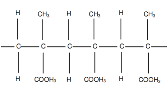
As its name suggests, PMMA is the polymer form of methyl methacrylate. Each monomer is comprised of an α-methyl, methyl-ester, and methylene bridge (methanediyl group). The monomers that make up PMMA are linked through addition, meaning that a hydrogen atom must be removed from each monomer for a polymer chain to be formed. The two carbons then bond, creating a new methylene bridge. The Chem Polymer Project lists several chemicals which react with PMMA, including: ethyl and methyl alcohols, chlorinated hydrocarbons, esters, ketones, organic acids, aromatic solvents, and lacquer thinners.

Methyl Methacrylate Monomer

Poly Methyl Methacrylate
Combustion Reaction
If one were to assume a one-step finite-rate forward reaction, combustion of PMMA would take place as follows:
![]()
However, when solid phase polymers are exposed to high temperatures, degradation reactions (following several reaction pathways) begin to occur which release combustible gaseous products. The mixture of these degradation products with an oxidizer makes for a highly combustible combination of gases. A paper by the National Institute of Standards and Technology states that PMMA undergoes a reversal of the polymerization reaction when it breaks down under thermal energy. This produces a large yield of methyl methacrylate monomers. The NIST also indicates that abnormal structures within PMMA (such as unsaturated end groups or head-to-head linkage within the chain) cause a decrease in thermal stability and ignition time, as well as an increase in burn rate. These abnormal structures are a common byproduct of the polymerization process of PMMA. As a thermoplastic, PMMA becomes pliable near its melting point, 140°C, and can be allowed to cool back to its original form. Thermoplastics are able to do this since no irreversible chemical reactions occur while it sets.The ignition temperature of PMMA in the presence of open flame is around 290°C.
Sources
Chem Polymer Project: http://chempolymerproject.wikispaces.com/Plexiglass-E-MgEb
Image 1 and Pichai Rusmee’s University of Utah Dept. of Mech Eng. Lab Notes: http://www.mech.utah.edu/~rusmeeha/labNotes/degradation.html
Paper by the National Institute of Standards and Technology: http://fire.nist.gov/bfrlpubs/fire95/PDF/f95104.pdf
Image 2: http://www.expertsmind.com/CMSImages/1766_Polymerization%203.png
Hybrid Rocket Fuel Grain Theory and Design Considerations
Last week, I posted a write-up which gave an overview of hybrid rocket engines. In this post, I plan to build on my initial review of the fuel port’s function by summarizing the large amount of information I have compiled through research. Finally, I will outline the parameters I plan to design my first fuel grain around.
Review of Fuel Port Function
A hybrid rocket engine, like most modern rockets, creates thrust by directing a flow of highly pressurized gases through a nozzle. The gases accelerating through the nozzle exert an equal and opposite force on the rocket, which is known as thrust. Recall from the overview of hybrid rocket engines that a hybrid engine ignites a mixture of fluid oxidizer and solid fuel to generate a stream of hot, high pressure gases. These hot gases are directed to the nozzle by the fuel port, which channels the gases. Since the fuel port is cut from the solid fuel grain, the cross-sectional area of the fuel port(s) changes as the combustion reaction uses up the solid fuel.

Common Fuel Port Geometries
The cross-sectional geometry of the fuel port in a hybrid rocket engine has a significant effect on its thrust curve. As the oxidizer flows down the fuel port, it is only able to react with the exposed surface area of fuel grain. Fuel regression during use causes the surface area exposed to the oxidizer to change and the cross-sectional area of the fuel port to increase. The free surface of the fuel port at an instant of time is referred to as the instantaneous burning area. The continuous change of the instantaneous burning area causes the pressure of the gases entering the nozzle to vary, which leads to an inconsistent thrust over an extended period of time. The image below depicts four common fuel grain geometries: Tubular (A), Star (B), Cruciform (C), and Rod and Tube (D).

As the burning area changes, the amount of thrust generated varies. This effect can be exploited to select or design fuel port geometries which give a favorable thrust curve for the mission to be performed by the rocket. In Robert A. Braeunig’s detailed write-up of space propulsion systems and Richard Nakka’s website on Experimental Rocketry, the thrust curves of the geometries in the above figure are explained as follows:
- A: Thrust increases progressively over time
- B: Thrust is produced fairly constantly until the fuel is used up
- C: Thrust decreases progressively over time
- D: Thrust develops relatively constantly until the inner rod becomes used up, causing the thrust to drop quickly
The tubular (A) grain pattern is the most common configuration used by hobbyists, largely due to a desirable thrust curve and a easy-to-mold fuel port geometry.
Fuel Grain Regression
According to Carolynne Campbell-Knight in her article for Space Safety Magazine, fuel grains are considered the most troubling aspect of hybrid rocket design. Ignition of the fuel grain, regression of the fuel grain, and oxidizer to fuel ratio shift during use are some of the difficult factors to design for in hybrid engines. Understanding of the way in which the fuel grain recedes is important for design of the combustion chamber, injector, and nozzle. The instantaneous burning area always regresses in the direction normal to the surface of the propellant. For this reason, the initial fuel port geometry and any existing hard features such as incombustible coatings, casings, or bulkheads will determine the thrust curve generated. To summarize, the geometric regression of the fuel grain (and therefore the instantaneous burning area) is dependent on:
- initial fuel grain geometry
- features which restrict or inhibit burning
Hybrid rocket engines are prone to having a low fuel regression rate relative to solid fuel rockets due to the chemical differences between the fuel grains used. This low regression rate may necessitate the use of several fuel ports, which comes with its own set of design challenges (addressed in the Volumetric Loading Fraction sub-section below).
Oxidizer to Fuel Ratio Shift
Oxidizer to fuel ratio shift (O/F shift) is the result of the instantaneous burning area varying while the oxidizer flow rate is held constant. In the simple case of a tubular grain geometry, the instantaneous burning area increases as the exposed surface of the fuel regresses. This causes the O/F ratio to decrease, which in turn results in a rich combustion mixture. An overly rich O/F mixture has the potential of causing power loss, fouled components, and incomplete combustion of the fuel grain. On the other hand, a grain geometry like the cruciform sees a loss of instantaneous burning area as the grain pattern regresses. If oxidizer flow rate is held constant during the burn, the O/F ratio will increase and the engine will suffer from a lean O/F mixture. Lean mixtures have higher efficiency than rich mixtures due to more complete fuel burn, but the resulting high temperatures can inflict damage to sensitive parts.
In complex rocket engines, O/F ratio can be manipulated by regulating the delivery of oxidizer to the fuel. An adaptive injector can respond to a changing O/F ratio by increasing or decreasing the flow rate of the oxidizer. I believe this to be beyond the initial scope of this project and difficult to measure and implement on a bench-scale engine, but investigating controlled injection would be interesting in the future as I gain experience with designing safe rocket motors.
Important Design Parameters
Propellant Density:
The mass density of the propellant is an important parameter used in the calculation of ideal thrust output and overall engine performance. The above formula holds only for homogeneous materials; when determining the mass density of the propellant I plan to compare the empirical and theoretical values. The difference will indicate the relative amount of impurities or imperfections in the rod.
Volumetric Loading Fraction:
The volumetric loading fraction is an indication of the amount of solid fuel relative to the amount of space available for fuel in the in the combustion chamber. It also represents the volumetric efficiency of the engine. As can be seen in the formula below, the total impulse delivered by the engine relative to the maximum deliverable impulse is a measure of the volumetric loading fraction. We then note that using multiple fuel ports to increase the available burning area (encouraging high regression rates) leads to an engine with poor volumetric efficiency. From this we can appreciate the importance of optimizing the chemical pairing of the oxidizer and fuel grain in order to maximize the regression rate of the fuel.

Port Area to Throat Area Ratio:
In his online article on propellant grain theory, Richard Nakka cautions that severe core stripping is likely to occur if the ratio of port area to throat area reaches one. This is due to the flow velocity through the fuel port being equal to the velocity through the nozzle throat (which is sonic if supersonic exhaust is achieved – more on nozzle theory in a later post). For this reason, a ratio which yields significant core-stripping is avoided in design. Charts of erosive burning port-to-throat area ratio values are available for a few common fuels. When using propellants for which the erosive burning ratio value has not been established, Nakka recommends a port-to-throat area ratio between 2.0 and 3.0 depending on the length/diameter ratio of the fuel grain.

Grain Length to Grain Diameter Ratio:
Nakka also comments on the ratio of grain length-to-grain diameter ratio, stating that as the ratio increases, erosive burning effects start to become a problem within the fuel port. This problem arises due to a mass flow differential along the length of the fuel port. Nakka suggests that a way to minimize these effects in a long fuel grain or narrow fuel port is to utilize a tapered or stepped fuel port profile along the long axis of the fuel grain. This profile will compensate for the longitudinal mass flow differential by modifying the cross-sectional area as the flow travels towards the nozzle.
![]()
Sources
Richard Nakka’s Experimental Rocketry Website – Design Parameters section: http://www.nakka-rocketry.net/
Space Safety Magazine: http://www.spacesafetymagazine.com/2013/07/12/hybrid-rocket-overview-part-2/
Robert A. Braeunig’s Website – Fuel Port Geometries: http://www.braeunig.us/space/propuls.htm
An Overview of Hybrid Rocket Motors
Combustion Rocket Engines
A common way of distinguishing between types of rocket motors is by characterizing the propellant they use. Although non-combusting rockets exist, most rockets convert chemical potential energy to kinetic energy by means of combustion. The three most prolific combustion rocket engine types are solid propellant, liquid multi-propellant, and hybrid. Simple solid-fuel rockets consist of a single ignitable propellant which, once lit, can not easily be throttled or extinguished. This is in contrast to liquid multi-propellant rockets, which harness the energy resulting from an exothermic reaction between a mixture of propellants. This type of rocket is easily throttled by controlling the propellant flow rate, but requires expensive injection systems and experiences large thermal fluxes across the combustion chamber. Both solid and liquid fueled rockets have seen extensive use in aerospace applications. Systems which have successfully used solid propellants include the Aim 9 Sidewinder Air to Air Missile, the LGM-30 Minuteman-III ICBM, and the solid rocket boosters which assist the Space Shuttle into orbit. Liquid multi-propellant rockets have seen a lot of use in booster stages including those used for the Soyuz, Saturn V, and Delta IV spacecraft.
Simple Hybrid Engines
Hybrid rocket engines rely on the combustion of two propellants in different states of matter. The propellants usually consist of an oxidizer in a fluid state flowing through a solid fuel, called a fuel grain, in a combustion chamber. The oxidizer and fuel are selected so that they react exothermically when exposed to an ignition source. The combustion of the propellant causes rapidly expanding gases to travel down the fuel port(s) until they reach the nozzle, where they are further accelerated before being exhausted. Hybrid rocket engines have a number of advantages over liquid multi-propellant and solid rockets. They are easily throttled, extinguished, or restarted by controlling the flow rate of the oxidizer.

The figure above depicts the combustion chamber of a simple hybrid rocket engine. The combustion chamber houses the solid fuel grain and contains the combustion reaction used to generate thrust. The combustion chamber in a hybrid engine is not necessarily pressurized, since it is possible to contain the pressure between the fuel grain, injectors, and nozzle. On more complex rocket motors, the combustion chamber can also house cooling systems designed to keep the combustion chamber and nozzle from degrading under high thermal stress.
The solid fuel grain is designed with a fuel port which allows the oxidizer to react as it is forced towards the nozzle. A fuel grain can have one or several fuel ports, and fuel port geometry can be simple or complex. In small scale rocket design, the use of one fuel port with a circular cross section is common, since the use of multiple fuel ports requires a more elaborate injection system and results in complex thermal and fluid flows through the combustion chamber. The nozzle and injection ports cap the ends of the fuel grain and ensure that pressure is not lost from the system except by way of the nozzle. Common materials used as the fuel-grain are polymers (Poly Methyl Methacrylate, Polyethylene, Poly Vinyl Chloride, etc.) and paraffin. Liquid or gaseous oxygen, nitrous oxide, and hydrogen peroxide are some of the most frequently used oxidizers in small scale devices. In the following few weeks of research, I will be posting documentation specific to fuel grain, oxidizer, nozzle, and injector selection and design.
Hybrid Engine Safety
Hybrid motors are inherently safe, since the solid fuel grain is inert when oxidizer is not present. For this reason, hybrid rockets are classified as having no TNT equivalence, while solid rocket motors are usually rated with a TNT equivalence within the order of magnitude of the mass of their fuel grain. Failure of a hybrid rocket engine would not result in a catastrophic explosion, since the fluid oxidizer is only able to mix with the exposed surface area of the solid fuel grain. Even with the combustion chamber full of oxidizer and an ignition source present, the lack of oxidizer actively flowing into the combustion chamber will prevent a reaction with explosive-level force from occurring in a hybrid. Pressure vessel failure due to over-pressure or fatigue is a risk present in both liquid multi-propellant and hybrid rocket engines, but this hazard is not specific to hybrids; it is present in all pressure-fed systems.
This hybrid rocket engine project will be termed “HRE #”, where the number is the iteration number.
Introduction to the Hybrid Rocket Engine Project
Welcome to my project blog!
Since their introduction in 1953, hybrid rocket engines have become an advanced technology in the aerospace industry. Scaled Composites’ SpaceShipOne and Virgin Galactic’s SpaceShipTwo have both successfully used hybrid engines to achieve manned suborbital spaceflight. Development of hybrid rocket engines is ongoing in many organizations such as Copenhagen Suborbitals, Orbitec, SpaceDev, Reaction Research Society, and the Bloodhound SSC (SuperSonic Car) group .
My motivation for pursuing this project is as follows:
- to gain experience in self-led research, design, fabrication, and evaluation
- to explore and develop my interest in propulsion systems and mechanical engineering design
I will be using this blog to document the design process and display my successes and failures along the way. The timeline for this project is from late May 2014 to the end of August 2014. Listed below are my primary and secondary objectives:
Primary Objectives
- Design and fabricate a small-scale hybrid rocket motor capable of accepting a variety of nozzles, fuel grain types, and fuel grain sizes
- Measure performance of the system as a function of geometric configuration of the fuel grain
- Develop a nozzle and fuel grain geometry capable of generating supersonic exhaust flow
Secondary Objectives
- Measure Oxidizer to Fuel Ratio Shift (O/F Shift), which is a cause of reduced chemical performance in hybrid rocket engines
- Experiment with a variety of oxidizers, polymers, and liquefying fuels
