
Rocket Fuel: Poly Methyl Methacrylate
Poly Methyl Methacrylate
A common material used by hobbyists as a fuel grain in hybrid rocket engines is poly methyl methacrylate, or PMMA. Widely known by trademark names such as Plexiglas, Lucite, and Perspex, PMMA is a common thermoplastic and is easily found in sheet form. I recently purchased an 8 foot long cast PMMA rod for use as the fuel grain in the first few tests of HRE I. Notwithstanding a few chemistry and materials engineering classes, my background in polymers is rather lacking. This drove me to do some investigation into PMMA and its behavior during combustion.
Chemical Composition
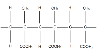
As its name suggests, PMMA is the polymer form of methyl methacrylate. Each monomer is comprised of an α-methyl, methyl-ester, and methylene bridge (methanediyl group). The monomers that make up PMMA are linked through addition, meaning that a hydrogen atom must be removed from each monomer for a polymer chain to be formed. The two carbons then bond, creating a new methylene bridge. The Chem Polymer Project lists several chemicals which react with PMMA, including: ethyl and methyl alcohols, chlorinated hydrocarbons, esters, ketones, organic acids, aromatic solvents, and lacquer thinners.
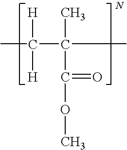
Methyl Methacrylate Monomer

Poly Methyl Methacrylate
Combustion Reaction
If one were to assume a one-step finite-rate forward reaction, combustion of PMMA would take place as follows:
![]()
However, when solid phase polymers are exposed to high temperatures, degradation reactions (following several reaction pathways) begin to occur which release combustible gaseous products. The mixture of these degradation products with an oxidizer makes for a highly combustible combination of gases. A paper by the National Institute of Standards and Technology states that PMMA undergoes a reversal of the polymerization reaction when it breaks down under thermal energy. This produces a large yield of methyl methacrylate monomers. The NIST also indicates that abnormal structures within PMMA (such as unsaturated end groups or head-to-head linkage within the chain) cause a decrease in thermal stability and ignition time, as well as an increase in burn rate. These abnormal structures are a common byproduct of the polymerization process of PMMA. As a thermoplastic, PMMA becomes pliable near its melting point, 140°C, and can be allowed to cool back to its original form. Thermoplastics are able to do this since no irreversible chemical reactions occur while it sets.The ignition temperature of PMMA in the presence of open flame is around 290°C.
Sources
Chem Polymer Project: http://chempolymerproject.wikispaces.com/Plexiglass-E-MgEb
Image 1 and Pichai Rusmee’s University of Utah Dept. of Mech Eng. Lab Notes: http://www.mech.utah.edu/~rusmeeha/labNotes/degradation.html
Paper by the National Institute of Standards and Technology: http://fire.nist.gov/bfrlpubs/fire95/PDF/f95104.pdf
Image 2: http://www.expertsmind.com/CMSImages/1766_Polymerization%203.png
Hybrid Rocket Fuel Grain Theory and Design Considerations
Last week, I posted a write-up which gave an overview of hybrid rocket engines. In this post, I plan to build on my initial review of the fuel port’s function by summarizing the large amount of information I have compiled through research. Finally, I will outline the parameters I plan to design my first fuel grain around.
Review of Fuel Port Function
A hybrid rocket engine, like most modern rockets, creates thrust by directing a flow of highly pressurized gases through a nozzle. The gases accelerating through the nozzle exert an equal and opposite force on the rocket, which is known as thrust. Recall from the overview of hybrid rocket engines that a hybrid engine ignites a mixture of fluid oxidizer and solid fuel to generate a stream of hot, high pressure gases. These hot gases are directed to the nozzle by the fuel port, which channels the gases. Since the fuel port is cut from the solid fuel grain, the cross-sectional area of the fuel port(s) changes as the combustion reaction uses up the solid fuel.

Common Fuel Port Geometries
The cross-sectional geometry of the fuel port in a hybrid rocket engine has a significant effect on its thrust curve. As the oxidizer flows down the fuel port, it is only able to react with the exposed surface area of fuel grain. Fuel regression during use causes the surface area exposed to the oxidizer to change and the cross-sectional area of the fuel port to increase. The free surface of the fuel port at an instant of time is referred to as the instantaneous burning area. The continuous change of the instantaneous burning area causes the pressure of the gases entering the nozzle to vary, which leads to an inconsistent thrust over an extended period of time. The image below depicts four common fuel grain geometries: Tubular (A), Star (B), Cruciform (C), and Rod and Tube (D).

As the burning area changes, the amount of thrust generated varies. This effect can be exploited to select or design fuel port geometries which give a favorable thrust curve for the mission to be performed by the rocket. In Robert A. Braeunig’s detailed write-up of space propulsion systems and Richard Nakka’s website on Experimental Rocketry, the thrust curves of the geometries in the above figure are explained as follows:
- A: Thrust increases progressively over time
- B: Thrust is produced fairly constantly until the fuel is used up
- C: Thrust decreases progressively over time
- D: Thrust develops relatively constantly until the inner rod becomes used up, causing the thrust to drop quickly
The tubular (A) grain pattern is the most common configuration used by hobbyists, largely due to a desirable thrust curve and a easy-to-mold fuel port geometry.
Fuel Grain Regression
According to Carolynne Campbell-Knight in her article for Space Safety Magazine, fuel grains are considered the most troubling aspect of hybrid rocket design. Ignition of the fuel grain, regression of the fuel grain, and oxidizer to fuel ratio shift during use are some of the difficult factors to design for in hybrid engines. Understanding of the way in which the fuel grain recedes is important for design of the combustion chamber, injector, and nozzle. The instantaneous burning area always regresses in the direction normal to the surface of the propellant. For this reason, the initial fuel port geometry and any existing hard features such as incombustible coatings, casings, or bulkheads will determine the thrust curve generated. To summarize, the geometric regression of the fuel grain (and therefore the instantaneous burning area) is dependent on:
- initial fuel grain geometry
- features which restrict or inhibit burning
Hybrid rocket engines are prone to having a low fuel regression rate relative to solid fuel rockets due to the chemical differences between the fuel grains used. This low regression rate may necessitate the use of several fuel ports, which comes with its own set of design challenges (addressed in the Volumetric Loading Fraction sub-section below).
Oxidizer to Fuel Ratio Shift
Oxidizer to fuel ratio shift (O/F shift) is the result of the instantaneous burning area varying while the oxidizer flow rate is held constant. In the simple case of a tubular grain geometry, the instantaneous burning area increases as the exposed surface of the fuel regresses. This causes the O/F ratio to decrease, which in turn results in a rich combustion mixture. An overly rich O/F mixture has the potential of causing power loss, fouled components, and incomplete combustion of the fuel grain. On the other hand, a grain geometry like the cruciform sees a loss of instantaneous burning area as the grain pattern regresses. If oxidizer flow rate is held constant during the burn, the O/F ratio will increase and the engine will suffer from a lean O/F mixture. Lean mixtures have higher efficiency than rich mixtures due to more complete fuel burn, but the resulting high temperatures can inflict damage to sensitive parts.
In complex rocket engines, O/F ratio can be manipulated by regulating the delivery of oxidizer to the fuel. An adaptive injector can respond to a changing O/F ratio by increasing or decreasing the flow rate of the oxidizer. I believe this to be beyond the initial scope of this project and difficult to measure and implement on a bench-scale engine, but investigating controlled injection would be interesting in the future as I gain experience with designing safe rocket motors.
Important Design Parameters
Propellant Density:
The mass density of the propellant is an important parameter used in the calculation of ideal thrust output and overall engine performance. The above formula holds only for homogeneous materials; when determining the mass density of the propellant I plan to compare the empirical and theoretical values. The difference will indicate the relative amount of impurities or imperfections in the rod.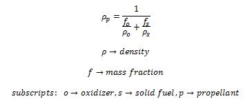
Volumetric Loading Fraction:
The volumetric loading fraction is an indication of the amount of solid fuel relative to the amount of space available for fuel in the in the combustion chamber. It also represents the volumetric efficiency of the engine. As can be seen in the formula below, the total impulse delivered by the engine relative to the maximum deliverable impulse is a measure of the volumetric loading fraction. We then note that using multiple fuel ports to increase the available burning area (encouraging high regression rates) leads to an engine with poor volumetric efficiency. From this we can appreciate the importance of optimizing the chemical pairing of the oxidizer and fuel grain in order to maximize the regression rate of the fuel.

Port Area to Throat Area Ratio:
In his online article on propellant grain theory, Richard Nakka cautions that severe core stripping is likely to occur if the ratio of port area to throat area reaches one. This is due to the flow velocity through the fuel port being equal to the velocity through the nozzle throat (which is sonic if supersonic exhaust is achieved – more on nozzle theory in a later post). For this reason, a ratio which yields significant core-stripping is avoided in design. Charts of erosive burning port-to-throat area ratio values are available for a few common fuels. When using propellants for which the erosive burning ratio value has not been established, Nakka recommends a port-to-throat area ratio between 2.0 and 3.0 depending on the length/diameter ratio of the fuel grain.

Grain Length to Grain Diameter Ratio:
Nakka also comments on the ratio of grain length-to-grain diameter ratio, stating that as the ratio increases, erosive burning effects start to become a problem within the fuel port. This problem arises due to a mass flow differential along the length of the fuel port. Nakka suggests that a way to minimize these effects in a long fuel grain or narrow fuel port is to utilize a tapered or stepped fuel port profile along the long axis of the fuel grain. This profile will compensate for the longitudinal mass flow differential by modifying the cross-sectional area as the flow travels towards the nozzle.
![]()
Sources
Richard Nakka’s Experimental Rocketry Website – Design Parameters section: http://www.nakka-rocketry.net/
Space Safety Magazine: http://www.spacesafetymagazine.com/2013/07/12/hybrid-rocket-overview-part-2/
Robert A. Braeunig’s Website – Fuel Port Geometries: http://www.braeunig.us/space/propuls.htm
